|
Variable Inlet Vanes to VSD Conversion |


|
rev. 2008-11-25

|
|
|
Variable Inlet Vanes to VSD Conversion |
|
|
rev. 2008-11-25
|
|
Existing Conditions
Air conditioning and ventilation to xxx is supplied by variable air volume (VAV) fan system xxx. Variable inlet vanes (VIVs) on the supply and return fans modulate to maintain the required duct pressure and air flow. The VIVs throttle air flow by creating flow resistance. Under these conditions, which occur during partial system load, the fans operate inefficiently.
Retrofit Conditions
We recommend replacing the variable inlet vanes and fan motor with variable frequency motor drives (VFDs) and inverter-duty motors on both the supply and return fans. The duct pressure and air flow will then be maintained by automatic adjustment of the fan motor speeds. The fan motors will draw less power because the fans will have less flow resistance to overcome.
<The new VFDs are electronic components, and although they are designed for continuous operation, they will occassionally fail. Since this fan system serves a critical area that must have cooling available at all times, we recommend designing the new system with manual bypasses. The bypasses will allow either fan to operate at full speed by diverting power directly to the fan motor if the VFD fails. To prevent the fans from over-pressurizing and damaging the ductwork, the VIVs must be left in place to limit duct pressure when the new system is in bypass mode. Under normal operation, the VIVs would remain fully open.>
Further Benefits
Application Details
Issues and Concerns
References
Analysis
Method 1: BIN Method
Existing Conditions:
To calculate the existing conditions, use the Reference Material chart/equation to estimate the existing energy consumption (in kWh) of the fan.
The most common method of calculating the consumption would be to use the BIN method. For each BIN, the analyst would:
| 1. | Estimate the air flow (in % of maximum flow) for each BIN. |
| 2. | Estimate the peak load of the fan in kW. For a fan where a BHP (Brake Horsepower) is available or an actual measurement is available, use this number. When unavailable, assume the fan is 75% loaded, so the load would be kW=HP x 0.75 x 0.746 [kW/hp]. |
| 3. | Calculate the load for each BIN (in kW) of the fan with a VIV using the Reference Material chart or equation. |
| 4. | Calculate the existing consumption (in kWh) for each BIN using the load and the BIN hours. |
Retrofit Conditions:
To calculate the retrofit conditions, use the Reference Material chart/equation to estimate the retrofit energy consumption (in kWh) of the fan.
Use the same method that was used for the Existing Conditions. For each BIN, the analyst would:
| 1. | Reuse the estimated air flows from the Existing Conditions. |
| 2. | Reuse the estimated peak load of the fan from the Existing Conditions. |
| 3. | Calculate the retrofit load for each BIN (in kW) of the fan with a VSD using the Reference Material chart or equation. If the individual VAV boxes are being controlled through the BAS system, use the Static Pressure Reset equation. If the VSD is controlled through a duct pressure sensor, use the Constant Static Pressure equation. |
| 4. | Calculate the retrofit consumption (in kWh) for each BIN using the load and the BIN hours. |
Reference Material:
The following chart shows various volume control methods:
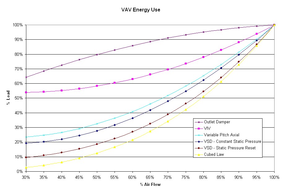
Outlet Damper - This is a worst case scenario, where the fan is running at full speed and the duct pressure is controlled through a damper located down stream of the fan. It is also the curve for when controls are no longer used, the duct pressure is allowed to run wild, and the individual VAV boxes control the air flow.
VIV - Variable Inlet Vanes are a common control method. They operate by creating a resistance at the inlet of the fan. They also create an initial swirl to the incoming air, which assists the fan, resulting in a better curve than the outlet damper.
Variable Pitch Axial - Axial fan with a variable pitch blade to vary the flow. This fan system is very close to the VSD.
VSD - Constant Static Pressure - Variable Speed (Frequency) Drive on the fan will give this curve if the fan speed is controlled to a constant duct pressure.
VSD - Static Pressure Reset - Variable Speed (Frequency) Drive on the fan will give this curve if the fan speed is controlled to a varying duct pressure. The duct pressure setpoint would depend on the actual VAV box positions.
Cubed Law - Ideal load for a given flow.
For calculating savings, use the following equation and constants:
Load (%) = C1 x Flow3 +C2 x Flow2 + C3 x Flow + C4
Flow Control Method |
Constant C1 |
Constant C2 |
Constant C3 |
Constant C4 |
Outlet Damper |
0 |
-0.53 |
1.20 |
0.33 |
VIV |
0 |
0.89 |
-0.50 |
0.61 |
Variable Pitch Axial |
0 |
1.28 |
-0.57 |
0.29 |
VSD - Constant Static Pressure |
0 |
1.45 |
-0.73 |
0.28 |
VSD - Static Pressure Reset |
0.93 |
0 |
0 |
0.07 |
Cubed Law |
1 |
0 |
0 |
0 |